Optimus' Basic Introduction to 3D - Why do the equations work?
Optimus/Dirty Minds^Nasty Bugs
Most parts of this tutorial were originally written for the 6th issue of our CPC diskmag, Ovation. Antitec decided to not include this article, because it was very big. In it, I was explaining how 3d rotation/projection works and then continued talking theoretically about what remains to do next, since my only practical experience is that I've coded 3d dots and nothing more. Via discussions, tutors, mathematical knowledge and my own logic, I have figured out how polygon drawing, shading models, z-buffering, lighting and everything else needed to build something more appealing works. It's just that I rarely find the time to continue building my humble software 3d engine. Months after I finished writting this tutorial, I created a line/polygon drawing routine but the results are funny because I just draw any polygon of my objects without having a polygon sorting routine. :) Enough months have passed since the last time. Anyways, that theoretical part is absent, I'd prefer to rewrite it another time once I have got more experience. But the learning basis for every newbie wishing to code some rotating dots is here. Which you can work alone through, in order to create some nice object shows with shiny lightnings :)
While this matter is a very simple one covered a lot of times before, what I wanted to give out through my tutorial is why the equations actually work. I can't remember one tutorial really explaining any of the maths, rather than giving the equations as they are, by only saying that they rotate points. Or, at least most of them doesn't prove the equations. If you know one that does, I'd like to read it. Some were giving matrices which would rotate or project points if multiplied with other matrices. The well known rotation and projection equations would appear if someone did the multiplications with a matrix of a 3d point with X,Y,Z variables in a piece of paper, but where do they come from? They suggested to use them without caring! My tutorial might not cover everything I'd wish, uncovered questions might exist, but at least it mirrors my desire to explain in detail, everything I went through, till I displayed a bunch of 3d rotated and projected dots on the screen, while trying to mathematically prove everything I can, limited by my knowledge. I will start by proving the 2d rotation equations of a single point, which we will use later to define the ones for 3d rotations. But let's first begin with a theoretical introduction in just one big paragraph.
The most basic introduction to 3D
You may wonder how everything starts, where is the beginning of life, universe and everything,.. or well, what is the base of all till the moment your eyes see a cool 3d world rotating around your head, shaded, textured, lighten with flashy effects, objects rotating individually to the whole world, cameras and other funky stuff! Everything starts with dots, or actually 3d points in a space with (X,Y,Z) coordinates each (also called vertices). These vertices construct individual objects (e.g. the player or monsters in a game) and some other construct static parts of the world (a Quake map, just another gamer's example :)). The objects rotate in 3d space around their center, and the whole world of all the 3d dots around the viewer's eyes. However, these 3d coordinates are just virtual data, so we have to find their real 2d coordinates on the screen. If we do this we can output correctly. We cannot only plot pixels, but also connect specific dots with lines to do a wireframe object. Remember also that each 3 specific pairs of dots could construct a 2d triangle which we can later fill to show a more solid version of the 3d object. The polygon filling can be flat, gouraud, textured, a combination of each and more. You may understand now that everything starts from some virtual 3d points, which have to be rotated (sometimes also distorted, wave, morph, if we want to make some other neat effects upon the objects formation in realtime!). After all the 3d calculations, we have to project the data in two dimensions upon the screen (I haven't heard of a true 3d screen, have you?) and then fill the triangles constructed by these 3d dots by using various shading algorithms, resulting in a final output looking almost like reality, far away from our starting virtual 3d points! I forgot only to tell you that there are also algorithms which help us to find out which polygons have to be drawn and which not ('cause they are behind other polygons or they are not facing the camera view, etc.) before drawing anything to the screen and there are also lights, cameras and much more. 3d graphics is a whole science and I will explain you a very tiny basic portion of them, suitable only for doing simple 3d dot object shows. Perhaps I will expand this tutorial into more advanced stuff through my personal learning/experimenting in the future.
2D point rotation
This part was originally written for a rotozoomer tutorial in Ovation 6. My 3d gfx tutorial referred back to this chapter later, because the 2d rotation equations were needed for applying them at the 3rd dimension. Tutors were using the knowledge one after the other in a chain.
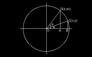
We will start with a scheme in order to help us in our quest. You need to remember a bit of the trigonometry you (may) have learned in school. Let's see! We have a point called C(X,Y) and we want to rotate it till it reaches the point D(Z,W). The rotation angle is b. a is the angle beetween OC and the X axis. And a+b is the angle beetween OD and the same axis.
Do you remember what sine and cosine means in a right-angled triangle? (The one which has one angle of 90 degrees.) Let's see in the OBC triangle what each of them is equal to:
COS(a)=OB/OC
SIN(a)=BC/OC
OC is called hypotenuse. In our case it is equal to r, the radius of the circle. The same happens with OD. OC=OD=r. BTW, OB happens to be equal to X and BC to Y. The two equations can be written this way:
X=r*COS(a)      (1)
Y=r*SIN(a)      (2)
BTW, these are the polar coordinate equations. You can apply them to express the position of a point by its angle (a) and radius (r), instead of X,Y. They can be used to achieve some very interesting circular effects like dot flowers, or circular scrollers. We will need them to prove the equations for rotation which are not depending on radius but only on the angle and the starting X,Y coordinates.
Now comes the most important part! D(Z,W) is the rotated version of C(X,Y). Our quest is to find these new Z,W coordinates! Remember that the rotation angle is b, but the angle beetween OD and the X axis is a+b. We will do the same trigonometry thing with the triangle OAD.
So..
COS(a+b)=OA/OD
SIN(a+b)=AD/OD
This means..
Z=r*COS(a+b)
W=r*SIN(a+b)
Hmm... now how about that? Are we stuck? Nope.. I opened my mathbooks from school to remember the trigonometric identities needed for that. I will write them down but not prove them. (I remember another tutorial doing that and it was big and hard enough, pure math stuff, not needed for understanding rotation equations.) These are:
SIN(a+b) = SIN(a)*COS(b) + COS(a)*SIN(b)
COS(a+b) = COS(a)*COS(b) - SIN(a)*SIN(b)
Our former equations are written now:
Z=r*(COS(a)*COS(b) - SIN(a)*SIN(b))
W=r*(SIN(a)*COS(b) + COS(a)*SIN(b))
Expanding..
Z=r*COS(a)*COS(b) - r*SIN(a)*SIN(b)
W=r*SIN(a)*COS(b) + r*COS(a)*SIN(b)
Now! Do you remember the equation we found for the triangle OBC called 1 and 2, some lines above? We know that r*COS(a)=X and r*SIN(a)=Y. Just replace them in our functions and we have:
Z=X*COS(b)-Y*SIN(b)
W=Y*COS(b)+X*SIN(b)
We have got them!
3D Rotations
Everything starts from virtual dots with 3d coordinates as I told you, which we have first to rotate. I found out how to rotate a dot in 3d space by combining my old 2d rotations. Yes! It was very simple. I will explain you in the next lines..
Let's think of a 3d object with its center located on the beginning of the 3 axes. Imagine that it rotates around the Y axis. Like a spinning top. Isn't it like the X and Z coordinates of each dot are rotating, except of Y which is not changing at all? (Ok, I know that it is like this, the matter is if I succeeded making you understand that!) So, if you got it, you may understand also that we can use the equations of 2d rotations, to rotate the X and Z coordinates of the object as we were in a 2d plane. We don't care about Y as the values remain unchanged. The same happens with the other 2 axes rotations. To rotate around the X axis we have to apply a 2d rotation upon the Y and Z coordinates of the 3d dots as long as X remains steady. You can think by yourself what has to be done with the Z rotation :)
So, we need to combine three 2-dimensional rotations in order to do a 3 axis rotation of our 3d object. If we suppose that our base 3d point is (X0,Y0,Z0) and the rotated version of it is (X1,Y1,Z1) then the equations are generally:
' --- Rotation around X axis ---

X1 = X0
Y1 = Y0 * COS(Xan) - Z0 * SIN(Xan)
Z1 = Z0 * COS(Xan) + Y0 * SIN(Xan)

' --- Rotation around Y axis ---

Y1 = Y0
X1 = X0 * COS(Yan) - Z0 * SIN(Yan)
Z1 = Z0 * COS(Yan) + X0 * SIN(Yan)

' --- Rotation around Z axis ---

Z1 = Z0
X1 = X0 * COS(Zan) - Y0 * SIN(Zan)
Y1 = Y0 * COS(Zan) + X0 * SIN(Zan)
Xan, Yan and Zan are of course the rotation angles for each axis. But beware! This is just an example!!! When I first went to use them as they are, I got unpredictable errors, rotations were distorted and more! And still a lot more things had to be corrected in order to finally see the first rotated 3d dots on the screen. That's why I have to guide you through my own older errors so that you don't get in big trouble too, till making your first 3d stuff..
Making them work
The main problem is that the 3 axis rotations won't work together. I can only rotate one and the same axis per frame or else my object will be distorted. Why? Imagine 3 rotations happening at the same time. At first, each point of the object would be rotated around X axis, based on the original ones (with X0,Y0,Z0 vertices). But the Y rotation should be applied now on the X rotated version of the object and not the base one. And when doing the Z axis rotation, we should apply it upon the X&emp;Y rotated version of the object. But the above equations are all rotating upon the base object. Which is wrong! Just imagine an object (a spaceship for example) which you want to rotate 5 degrees on X, 10 degrees on Y and 15 degrees on Z. You would rotate 5 degrees from the base object in X axis and then rotate the already rotated object around Y at 10 degrees, and the Z rotation will follow upon the already X and Y rotated object, rather than always depending on the base object because this way we cancel the previous axis rotations. It was stupid to rotate all axis upon the base object of course! It's not logical this way. I may had theoretically written the above equations at the very first time of exploring 3d rotations, but they were practically wrong when combined together..
I have just spoken about object (a set of vertices) rotation instead of point rotation while my equations were still applied upon one single point. I will continue showing you the old ones for it's easier to write and talk theoretically, just only imagine that instead of X0,Y0,Z0, you have X0(i),Y0(i),Z0(i) arrays of an object constructed by i vertices. It's the same thing. I hope I am not confusing anyone by this omission.
There was one more logical trap till I succeeded to finally and happily see my 1st 3d points! But we will see both errors corrected in the code below..
' --- Good Rotation around X axis ---

Y1 = Y0 * COS(Xan) - Z0 * SIN(Xan)
Z1 = Z0 * COS(Xan) + Y0 * SIN(Xan)

' --- Good Rotation around Y axis ---

X1 = X0 * COS(Yan) - Z1 * SIN(Yan)
Z1 = Z1 * COS(Yan) + X0 * SIN(Yan)

' --- Good Rotation around Z axis ---

Xp = X1
X1 = Xp * COS(Zan) - Y1 * SIN(Zan)
Y1 = Y1 * COS(Zan) + Xp * SIN(Zan)
What is this now? There are a lot of uncomprehensible things to explain to you. Pay attention because I am not sure how good am I at teaching, and some points are hard to explain properly.
Let's take it from the beginning. The first rotation is allowed to be calculated by using Y0 and Z0, 2 of the base object's coordinates. X remains unchanged. But the second rotation has to be applied upon the new coordinates of the X rotated object and not the base one. Though we still use X0 there. Why? Because it hasn't been changed in the first rotation! Notice also that we don't need to write X1=X0 in the first rotation. That's because X1's value will be changed after all in the second rotation based on the base X0. Though, the second rotation is also based on Z1 and not Z0 now. Z1 is the rotated version of Z0 that we calculated in the X rotation equations. The Y rotation happened upon the X rotated version of the object as we wish. Now about the 3rd rotation. All should be based upon the X&emp;Y rotated object. But there is a trap in the way we write the equations. Do you see that I put X1 into Xp, which I use in the 3rd rotation equations instead of X1? Why? If I used X1 in the last equations instead of Xp, the first equation would work fine. But what about the second one, the one which calculates Y1? It would be based on X1 which was just previously changed! But we don't want that, we want that X1 will be the one taken from the rotated object exactly after the second rotation. If you do the mistake there will be a distorted rotation, not as it should be. We just protect Y1 by first storing X1 to Xp and doing the calculations with that. Why hasn't this happened in the second Y rotation you will ask? Just because it happened that we had used X0 and not X1 there, so there was no problem there! Ok, it's perverse, I think you hit your head in the wall now :)
Actually these things may be confusing but it comes from an older code where I tried to reduce the calculations at the same time. It happens that I have the object X0,Y0,Z0 coordinates stored in an integer form, while X1,Y1,Z1 are floating points and thus it's profitable to use base object coordinates as much as I can before the 3rd rotation where it's not allowed anymore. Be careful also that this piece of code which succeeds to rotate 3 axes at the same time, has to remain exactly as it is, X before Y before Z. Don't spoil the raw it is running, or else you'll have to change the equations. If you moved the Z rotations at the first lines, these one should be based on X0, Y0 and not XP(X1),Y1. You had to change a lot of what I did in here. The first equation is always applied only upon the base object and the other two use data from the previous ones.
About matrices
I hear someone screaming "matrices?"! Perhaps this one solves the confusion that my equations might bring. Matrices are some mathematical rectangle thingies with a lot of data organised in raws and columns, which are used to automate several calculations into a more compact form. You can have one final matrix doing all the 3 axis rotations at once for example, by multiplying it with another matrix representing 3d point coordinates! There is a special algorithm behind matrix multiplications as with other matrix operations. As far as I know, my own equations are mathematically fine, it's just that the matrices used in 3d are a different way of representing the same thing. Then, why using them instead of my simple equations? Someone told me they could release us from additional calculations, someone else that they had to be used in more complex 3d engines or else these would start being uncomprehensible. It's an advanced thing I guess, not needed to be used for just a simple 3d object rotation but vital for 3d worlds with individual rotating objects, cameras, inverse kinematics, etc. I Just want to ensure you now, that my own equations do the same thing in reality. Also, I won't talk about it now, because I haven't used matrices in 3d yet (but I do know matrix operations from school and university). My current concern anyway, was to explain why the common equations also found inside matrices, work like this. Perhaps I'll talk about applying matrices in a 3d engine another day, when I will extend this tutorial.
Translations
Oh, btw you can also move/scroll your 3d object while rotating! This is called translation. I remember having done a small mistake while combining it with rotation. Normally, you just have to add a movement increment at each coordinate of the base object to do that. But please, first rotate the base object around its center and then move it! This was another blatant mistake I did at my first experiments. If you first translate and then rotate, you will make it rotating around a far central point and not around its own center as it would be preferable. Btw, have I told you before that these equations would work nicely if applied upon a base object with it's center at (0,0,0)? This is their rotation center and the dots will rotate around this point and nothing else if applied. So first rotate and then translate! (Except if you want to do something nasty ;) This way the object will rotate independently around it's central point while (and after that) moving everywhere in hell around the 3d space!
The code for that is simply:
X = X1 + Xpos
Y = Y1 + Ypos
Z = Z1 + Zpos
X, Y, Z are the final 3d points, translated versions of the rotated X1, Y1, Z1 we got from the 3 axis rotation equations. Xpos, Ypos and Zpos is how far from the (0,0,0) point, the center of our object will be. The 3Zero point is the central point upon the plane of the screen, in our virtual view at least. In some engines, positive Z is what the eye can see (what is behind the plane of our screen), in some others it's the opposite. In my own it's the positive Z that can be seen.
3D Projection
We still haven't displayed anything on the screen, because we have first to project the 3d coordinates in 2d screen ones. In fact we can still ignore Z and output points in X,Y upon the screen, though it won't look that much 3d in our eyes. In fact, I know some oldschool demos which avoided doing projection in order to gain speed and it was not that bad but still not real 3d. Like the great 3d cubes part in Elysium/Sanity Amiga demo or the amazing 3d dots part in Oneder/Oxyron or Y2KBug/Plush in C64. But if you have a modern computer, you'll definitelly have cpu time to project too :)
So we do have the 3d coordinates, what now? The screen wants to eat 2d ones! Someone could just ignore the Z1 coordinate of a point and output the 3d points by writing pixels at (X1,Y1). But this would not look like 3d as I said before! Just imagine a cube with these 8 3d points, specifically 4 points with Z=-1, these being (-1,-1,-1), (1,-1,-1), (1,1,-1), (-1,1,-1) and 4 points with Z=1, these are (-1,-1,1), (1,-1,1), (1,1,1), (-1,1,1). If you ignore Z then the 4 points with Z=-1 would be displayed on the screen exactly at the same places as the ones with Z=1. But that's not a 3d thing! From our human experience, the points of the cube that are further from the viewer are closer to the center of the horizon, which is the middle of the screen aka (160,100) in 320*200 resolution. This corresponds to the point (0,0,Z) in our 3d world.
Anyway, you see that Z has something to do with the final Xscreen and Yscreen coordinates were we have to plot our tridi stuff :) BTW, I never found them myself as I did with the 3d rotations, always used them without knowing how do they work. Till I found a nice tutorial one day, explaining or actually prooving the equations. The tutorial is called "Why divide by Z? Unraveling the geometry behind perspective projection", written by Toshi Horie, which gave me a great amount of help in order to understand why these equations actually project and I have written the proof and explanation based upon that. Without it I would be still searching as it hasn't happened to fall upon another explanation to this matter around the net. BTW, Toshi is the man who organises the pure Quick Basic democompos and has written a lot of QBasic demoeffects, texts and tutorials on his page. You can also read his tutorial at http://www.ocf.berkeley.edu/~horie/persp.txt.
So, as we said, the Xscreen and Yscreen coordinates are dependent on the X,Y and Z coordinates of a 3d point. And a more far Z will move Xscreen and Yscreen more close to the center of the horizon. I will present you first the equations in general:
Xscreen = 160 + X * Perspective / Z
Yscreen = 100 - Y * Perspective / Z
Ok, 160 and 100 are just values in order to center our virtual positions in a 320*200 resolution. The minus point in Yscreen is chosen to reverse Y from Cartesian to screen coordinates (because in computers, Y=0 is the top and by increasing Y you move down, while the opposite is happening in Cartesian coordinates). Perspective is a stable value (could be changed though at each frame to produce a weird perspective effect) and I have heard that 256 is usually a good value. Though, I don't really know yet if there is a real mathematical value for it that can be found. But we will see about it later in the proof of the above equations.
If you have noticed, a 3d point will tend to reach the center of the screen (and of the horizon too) when projected in 2d screen coordinates, as bigger the Z coordinate goes. A realistic and practical fact too. When Z is very big, Perspective / Z tends to be very small making X reaching almost zero. So Xscreen->160 and Yscreen->100 even if never touching theoretically. Someone could say that this is just an aproximation of reality. But someone else would ask for a mathematical explanation, and yes there is one! A practical explanation, even if not proved, but just doing its work would be fine for some, but personally I am not satisfied if someone doesn't give me a more mathematical explanation, especially for the complex things where the equations couldn't be popped out from the mind of a coder so easily. And that's why we won't stay on the practical explanation only, there is more to burn.
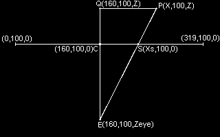
A scheme will help us in the proof of the projection equations. Imagine that this is a vision from above the ceiling to the floor (top-down view of screen, sliced at y=100). The horizontal line that cuts the triangle is the plane where the screen outputs. E is the viewer's eye, so from the opposite side of the horizontal line (where Q and P is) is everything that is behind the screen.
E(160,100,Zeye): The eye of the viewer
C(160,100,0):    The center of the screen
                 (We have estimated though that zscreen is 0)
P(X,100,Z):      A 3d point at Y=100 and X,Z varying
S(Xs,100,0):     The coordinates where you would plot the 3d
                 point on the screen
Q(160,100,Z):    Just another point necessary for the proof
Now we will use something you may remember from Geometry. Similar triangles. The triangles named this way are the ones with the shame shape but of different sizes. They have several properties like that each angle of a triangle is equal to the equivalent ones from another triangle similar to it. Another property (and the one which I will use here) is that their corresponding sides are proportional, meaning they are magnified by the same amount, and thus the ratio between the corresponding sides is the same. This means that the ratio of the corresponding sides of the triangle is the same for ECS and EQP! Which means:
          EC         CS
         ----   =  ------
          EQ         QP
EC is equal to the distance of the eye from the screen. I will leave it as Zeye for the moment..
EQ is the distance of the virtual 3d point from the screen plus EC, this means Z+|Zeye| = Z-Zeye since Zeye is in front of the screen and negative (we suppose that the viewable 3d points have a possitive Z in our little engine, this differs in each engine as I have said above).
CS is Xs-160.
QP is X-160 (if we suppose of course that we are working in 320*200 resolution).
         Zeye        Xs-160
       --------  =  --------
        Z-Zeye        X-160
Remember that we want to find an equation giving us Xs, so we will solve this for Xs:
              Zeye*(X-160)
        Xs = -------------- + 160
                 Z-Zeye
Now! The screen and virtual coordinates in the way we started the whole scheme are equal. I mean, the X coordinate of the center of the screen is 160 and this also applies for the coordinate of a 3d point. But we wanted that a point at X=0 would be displayed at Xs=160 on the screen. To do this we add 160 to (X-160) so that this happens. Zeye*(X-160+160)=Zeye*X.
              Zeye*X
        Xs = -------- + 160
              Z-Zeye
Now the things are getting incomprehensible for a bit. Or perhaps I think this one is still not the perfect explanation, or it could be a bit of aproximation too. Toshi is doing something I don't understand that much, he sets Z-Zeye --> Z. Remember that Zeye is supposed to be a stable number. Actually, Zeye is a very strange thing, cause I don't know how much the distance of the imaginery viewer from the screen, matters to the realistic 3d projection. Still, Zeye has a big role on how projection will look like! You should try changing it to see the effect it has. (It's the perspective variable in the first equations.)
(BTW, I just tried to understand a bit the Z-Zeye --> Z approximation. I think he adds Zeye: Z-Zeye+Zeye=Z in order to connect the virtual 3d coordinates with the Z screen cordinates, which are also virtual, though. :) Something similar like we did by adding 160 to X-160 in the previous version of the equation, but now adding Zeye in order to move Z=0 to be picking into the viewers eye? That must be the explanation I believe. I am really sorry for any incomplete explanations here..)
              Zeye*X
        Xs = -------- + 160
                Z
And we do have the first equation from above:
Xs = 160 + X * Zeye / Z
Xscreen = 160 + X * Perspective / Z
BTW, another point. We supposed that Y is 100 for every point in our scheme. But would the proof work if it was done in another height? Of course it would! Because if we move along Y, then the X and Z coordinates of the triangle are not changing, they are all the same. In fact as you can see from the equation, the whole calculation has no Y coordinate in it, it's totally independent! It's all fine and it works well for any Y.
We also have to find the equation for Yscreen. I will not write it here though, 'cause it's exactly the same logic as the one we did now (just the scheme is now different, a sideways view towards the screen in a Y slice of it at X=100) and it will add unecessary size to the article. Think only that several things apply in the same way. Adding 100 to (Y-100), the coordinate X being independent with the Yscreen equation, etc. You can still take a look at it in Toshi's tutorial (generally if you didn't understood something here, you may understand it there, the explanation is bigger) or try making it by yourself :)
I admit that this proof was pretty hard and that there are several things that I am not really sure how right they are. Like that it was a bit of math and practical approximation too. It's not the best thing and I couldn't research it more for the moment to clear some questions that I also have, it is still a little confused for myself too, but I think it seems preety much logical and a nicer thing than explaining nothing at all. I am only sorry if there are some mistakes in it, 'cause I was not 100% ready to totally understand and explain it. Another day I may research it more and upgrade this 3d tutorial and put it in my website.
Update: Exactly my thoughts, after rereading and correcting some things in my old Ovation 6 article. There exist still a lot of strange problems to solve, which I will cover in future updates of this article (I will add more things, making it a big explanation of 3d gfx, from the beginning till very advanced things) as long as I am learning.
For example, we could avoid X-160->X or Z-Zeye->Z by directly declaring Q(0,100,Z) as we wish the middle of the virtual 3d world, to coresspond with the middle of a rasterline on the screen (X=160). We could also directly say that Zeye equals to 0 (upon the screen plane), because the 3d world is like what a camera shows and if an object comes and hits you straight on your face, it's like it reaches very close to Zeye. We want that zero will be like hiting into the camera's eye and that a big Z (positive) will be far away in our view. perhaps Zeye would be diferrent if we had a moving camera not staying at (0,0,0), but that's a matter to take care in another tutorial. Also, if we'd set Zeye to zero then why Zeye*X is not equal to zero too? And why Zeye became perspective??? Actually,. I guess I said something wrong above. Zeye is not equal to zero, but Z happens to be equal to Zeye, or we add Zeye to Z-Zeye in order that the viewers eye will be virtually upon the plane of the screen. Z and Zeye and the plane of the screen are just some variables we don't know, and these approximations had just to do with the relationship beetween them. It's a better thought..
The tutorial has to end here, even if I feel I got confused at the end. I haven't written a totally complete and objective one, rather than my personal experience through making the first steps on 3d graphics, accompanied with all of my questions, mistakes and mathematical proofs of what I went through. It might be interesting to newbies who actually wish to get a clue of why 3d equations work like this, from a newbie in 3d software engines. You could ask me any questions you want, correct me or explain me anything I didn't covered well. Have a look at Toshi's tutorial too about projection too (http://www.ocf.berkeley.edu/~horie/persp.txt), perhaps it covers what I didn't manage to explain very well in here.